

Please read these instructions carefully before install your Digital Devices product.
To download the latest drivers and updated manuals check out our website www.digitaldevices.de.
For further contact details please browse to the end of this manual.
Note: We reserve the right for technical changes as well as changes in form, color and weight.
- Safety Instructions
- Product Features
- Technical Data
- Scope of Supply
- Initialization
- Installation
- Connection diagram
- Driver installation
- Digital Devices Control Center
- Functions
- Accessing the DD Control Center
- Hardware
- Signal setup
- Diagnostics and maintenance
- Software and applications
- Digital Devices TV
- Third party TV software providers
- Technical drawing
- Extensions
- Troubleshooting
- Imprint & Contact
Safety instructions and hazard notices
You have purchased a product for installation in PC systems.
Please read the following safety instructions carefully to avoid damage to persons or the product during use. Also obey the instructions in your PC manual.
Please provide the manual to people who carry out an upgrade or upgrade (also in case of resale).
Important safety instructions
- Installation requires knowledge with PC systems and may only be carried out by experienced users and trained staff.
- Never allow children to play with electrical appliances. They can not recognize hazards.
Disconnect your PC from the power supply before doing any work, and then wait a few minutes for all components to cool down before performing any work. There is a risk of electric shock when connecting to the power supply, which can be fatal.
- The power plug must be accessible in order to allow disconnection from the power supply in case of danger.
- Never bridge connections in the system or the power supply fuse, as there is a risk of electric shock.
Hazard information to work on your PC
- Do not plug or unplug any cables when the PC is switched on (not even the antenna cable).
- You should statically discharge prior to any work, for example by touching a grounded object.
- Use only components and cables in perfect original condition. Defective devices and cables must be replaced.
- Use the card only at the intended connections (PCI Express or data port) and do not apply force during installation
- The card / module must not come into contact with moisture or chemical solvents. Cards / modules which come into contact with liquid are to be sorted out.
- On no account use tools (e.g. screwdrivers) to reach hardly accessible places in the PC. Power supplies carry voltage even after being switched off, therefore there is a risk of (lethal) electric shock.
- Small parts such as screws can cause short circuits and should therefore not be located inside the PC.
- Do not use the card / module and PC outdoors. Cables for indoor use must not be used outdoors.In the event of problems, defects or questions, please contact your supplier.
Disclaimer of liability
The following points will result in the loss of liability, guarantee and warranty claims:
- Use of defective or modified parts and cables. Or parts and cables which have come in contact with liquids
- Failure to comply to safety instructions or installation by non-qualified persons
- Use of non-approved replacement parts
Electromagnetic compatibility and disposal
- The guidelines for electromagnetic compatibility must be adhered to when connecting the TV card / module.
- Electrical components must be disposed properly and do not belong in the household refuse.
Product Features
Highlights of the DuoFlex-Expansion module
The DuoFlex series is a dual-tuner extension for existing cards, bridges and network tuners such as the Octopus Net.
Designed and produced in Germany in addition to proprietary support by the manufacturer ensure a continual advancement of many software products.
Particular emphasis has been placed on environmentally friendly Green IT with low energy consumption and without environmental hazardous components.
Technical Data DuoFlex S2
Identification
- EAN: 4260217681270
- Part No.: 091610
Product category
- Dual tuner expansion module for DVB-S2
- An existing card with expansion port is required
Satellite characteristics
- Symbol Rate: 1 MSym to 67,5 MSym DVB-S2
- LNB Power:
- 4x Max. 19V
- 1A pulse current
- 500mA continuous current
- overcurrent protection
- Short-circuit protection
- L-band: 950 MHz to 2150 MHz
- DVB FEC: (Auto Spectral Detection)
- Full DiSeqC 2.X support
Unicable for DVB-S (Single Cable Routing)
- Unicable® compliant: SCR / Cenelec EN 50494
- JESS® compliant: Cenelec EN 50607
- On Windows PCs the support is already enabled by the driver; no additional support is required by applications.
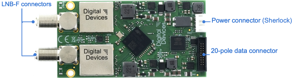
Connections
- 20-pin data port for connecting to existing Digital Devices cards (Cine, Octopus Bridges, Octopus CI module) or network tuners (OctopusNet)
- 2 input F-connectors (IEC 60169-24) (supports any required power supply to the LNB)
- Sherlock connector for power supply. (Power can either be supplied by a mains adapter or by cards with a Sherlock connector, such as Cine S2 v7)
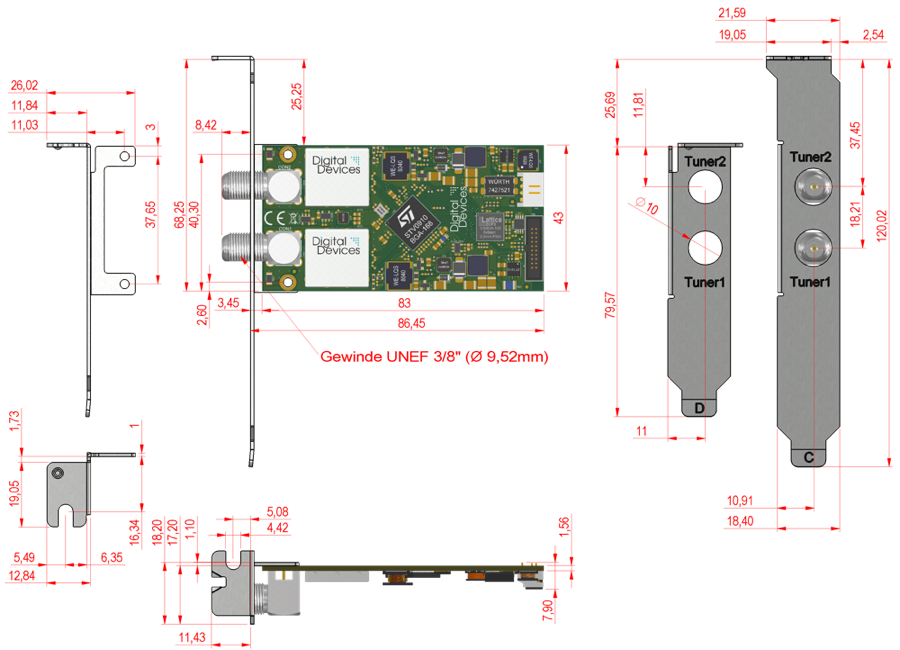
Dimensions
- H 43 mm, L 83 mm, D 14 mm
Power consumption
- 12V / 260mA = 3,1W 2*DVB-S2
Power supply
- 12V only ( 9-17V )
Supported operating systems
- Linux (Kernel 2.6 or higher)
- Microsoft Windows® XP(SP3), 7, 8, 8.1, 10; (32/64 Bit)
- Windows® Media Center compatible
System requirements
- Dual Core Intel® oder AMD® CPU
- 512 MB RAM
- a free slot or another eligible mounting space (no PCIe slot required)
- Digital Devices Cine or Octopus series card with connectors for extensions or Digital Devices network tuner (OctopusNet)
Enviroment and safety
- Manufactured and designed according to European ISO / DIN guidelines and environmental standards.
- RoHS compliant
- WEEE DE 99353762
Scope of Supply
- DuoFlex S2 v4 Dual Tuner expansion module
- Quick Install Guide (Print)
- Driver and manual (online)
Initialization
Note: Make sure to follow the safety instructions in this manual and in the user manual of your PC.
Initial preparation
- Carry out a backup prior to the installation process.
- Switch off the PC and disconnect the power supply. Now other external cables can be disconnected.
- Put the PC on a stable surface in order to access the backside easily.
- Wait a few minutes until all parts have cooled down before opening your PC and continuing the installation process.
Note: To prevent an electrical short circuit, newly acquired equipment and cards should not be put into operation until they have reached the surrounding temperature.
- Attach the slot bracket to the card or module if necessary and use the screws provided with the product.
Note: Depending on the measurements the card comes with two slot brackets (Full Profile and Low Profile). Slot brackets in various designs are available separately.
Installation of the expansion module
Note: Electrostatic Discharge (ESD) can damage internal components of the PC. Hence, you should discharge before working on the system, for example by touching a grounded object.
- Open the housing as described in the operating instructions of your PC.
- Locate a suitable PCIe slot and remove the slot cover.
- Insert the module into the slot vertically and tighten the screws of the slot bracket until it is fastened. Be careful not to damage any surrounding components.
- Connect the expansion module to the expansion connectors of your main card (Cine series or Octopus series) utilizing the supplied ribbon cable TAB sequence ascending.
Note 1: Make sure to use only original Digital Devices data cables for connections. For connections with tuner modules, cables with a ferrite core should be used.
Note 2: Make sure to connect the cable properly if dealing with an older DuoFlex module. The red wire of the cable must be pin 1 on the module or on the card (red wire at the bottom). For newer types, the connections and cables are protected against polarity reversal.
- Link the power supply of your module with a connector from your power adapter or the connector of your card (if available)
- Close the housing
- Reconnect any disconnected cables
- Connect the antenna cable to an antenna input port of your TV-card or to your tuner module
- Finally, connect the power cord to the PC and turn it on.
The module is managed like your existing card or module within the Digital Devices Control Center. The integration is seamless, you do not need to do anything.
Notes on data connection
If multiple modules are utilized, connected tuner modules are identified in the system as follows, depending on the TAB used:
- TAB 1 to Octopus series -> Tuner 1 & 2
- TAB 2 to Cine or Octopus series -> Tuner 3 & 4
- TAB 3 to Cine or Octopus series -> Tuner 5 & 6
- TAB 4 to Cine or Octopus series -> Tuner 7 & 8
Make sure that tuner extension modules are connected to smaller TABs of the Cine or Octopus series in terms oft numeration than the DuoFlex CI.
Connection diagram DuoFlex S2
Unicable®/Single Cable Routing
- Single cable routing according to EN50494 or EN 50607 allows supplying several TV receivers with only one cable. Depending on the technology used, up to 32 tuners can be supplied with a single cable. Prerequisite is a LNB, Stacker or multiswitch according to Unicable® or Jess® standard.
- The two connectors of the card are to be concentrated into a single cable via a splitter.
- The splitter must be Unicable® compliant and ensure DC pass-through for all connections.
- Unicable® frequencies and channels are being allocated via the DD Control Center.
Driver installation
No driver installation is required for your expansion module, it is integrated into the system via the base card.
Digital Devices Control Center - Basic configuration
Version 3.1 (06 2020)
The Digital Devices Control Center is included in driver version 2.7.0.108 or higher and is used to manage Digital Devices DVB-products on Windows systems.Network tuner configurations can be set via WebInterface or Octopus Cast Tool.
Note: This manual describes the relevant points for your product. A detailed description can be found here:
Functions
The following settings and functions can be adjusted in the DD Control Center:
- Setting operating mode (Unicable® system)
- Assigning reception mode (DVB-S/S2 as well as T/T2 and C/C2)
- Hardware information and diagnostic capabilities (Tunerlog, signal strength, temperature)
- Assign tuner to CI (if available)
- Access to CAM menus (if available)
Accessing the DD Control Center
Since driver version 3 the DD Control Center is integrated into the Windows Start menu and can be accessed there (up to version 2 it was accessed via the control panel).
For certain functions (adjusting driver settings) it may be necessary to run the application as an administrator.
Hardware
Connected hardware is displayed under Devices. For each base card, a menu item is created for selection.
If the card is equipped with expansion ports, those are displayed in the main screen, as well as the DuoFlex modules connected to them.
For diagnostic purposes, hardware data is available, which is presented in greater detail within the Diagnostics + maintenance section.
If installed cards or modules are not displayed properly, it must be checked whether they are connected correctly or not.
Signal Setup
Setting up Unicable® reception (DVB-S/S2)
Digital Devices cards and modules can be configured for Unicable® reception according to EN50494 and EN50607. The device is set up in the Tasks menu under Unicable® reception (DVB-S/S2)
(Exception: Cards from the Max series, for which this option is located in the menu _Devices)_
Note: Different names for Unicable® and Unicable IIÆ may include: JessÆ Single Cable Routing (SCR) or single cable solution.*
- Option normal operating state when using a standard SAT system / cabling. There are no other options available.
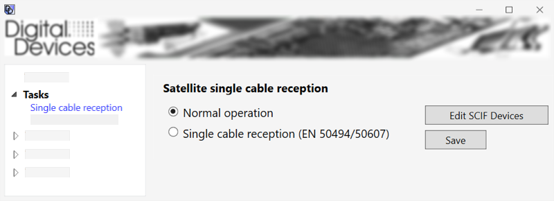
- Option Unicable® system according to DIN 50494/50607 when using a Unicable® receiving installation.
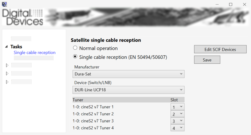
The corresponding manufacturer of the LNB or multiswitch can be selected in the upper drop-down box. Then the model can be selected in the lower drop-down box.
If the existing model is not listed, alternatively another can be selected if it uses identical frequencies and is not PIN-protected.
When the selection is done, all tuners that can be configured for Unicable® reception are displayed under Tuner .Slot* assigns frequencies to individual tuners.
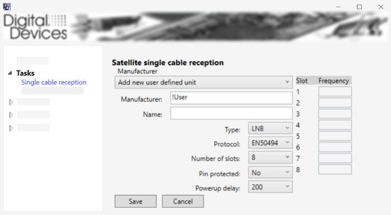
Edit SCIF Devices offers the possibility to create a specific entry, which is then destined for manufacturer and model selection.
Pin Protected
If the Unicable® multiswitch / LNB features a Pin Protected function, the option is displayed in the Digital Devices Control Center.
These PINs must be entered at the corresponding ports in the Control Center.
Usually the PIN specifications are defined by the LNB or multi-switch and can be found in the operations manual.
Note: If the function is activated, the devices exchange a PIN with each other so that no frequencies are used that are not intended for the respective receiver.
Diagnostics and maintenance
The Digital Devices Control Center provides functions for diagnosis and maintenance of your cards and modules.
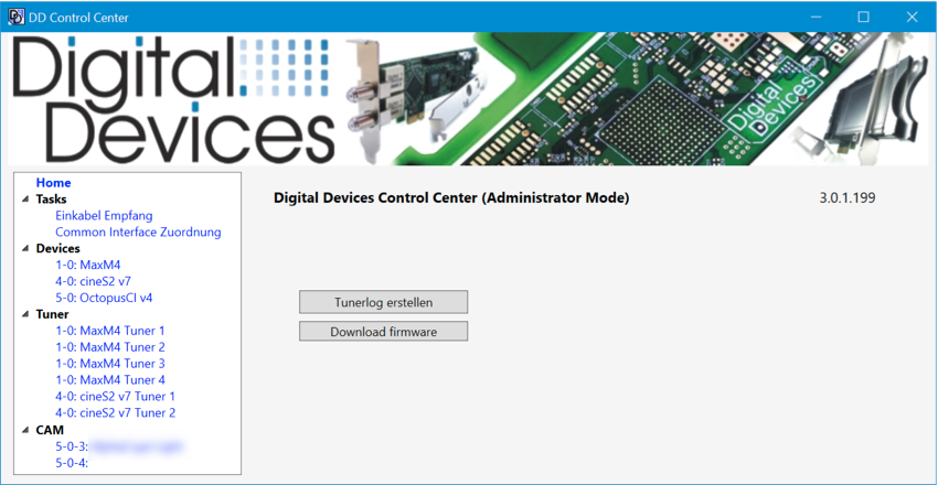
Show driver version (Homescreen)
The installed driver version is displayed in the homescreen. To check if a newer version is available, please visit our download page https://digitaldevices.de/downloads/treiber/ .
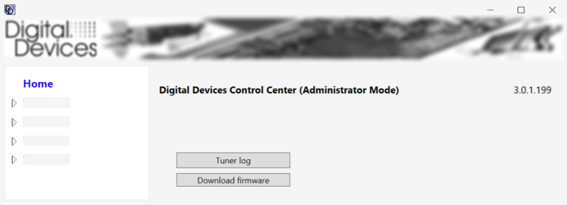
Create tunerlog (Homescreen)
Creates a detailed event list of the last seven days about the installed cards and modules. The report shows the signal values and in case of problems facilitates assistance regarding the analysis. The created file is saved to the desktop.
Firmware Download (Homescreen)
Redirect to the download page for firmware updates
Firmware updates can be downloaded here and then installed by using the provided routine.
Under Devices a button Firmware Update is displayed for cards for which an update is available. This button starts the update process for the selected card. The update process can be carried out for several cards one after the other.
After installing all desired updates, the PC must be shut down, a simple restart is not enough. After the next start, the update is completed.
Note: No firmware updates are available for expansion modules
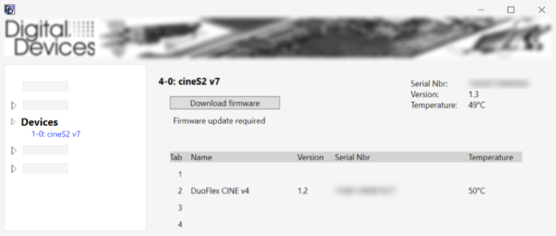
Detailed information about standard cards and extension modulesv (Menu Devices)
In the menu Devices a menu entry is displayed for each basic card.
If a selection is made in the menu, the main screen displays detailed information for the selected card and connected extensions:
- Serial number
- Firmware
- Firmware updates (if available)
- Temperature
Note: For the Octopus CI S2 (Pro and Advanced) and Octopus Duo CI, the bit rate of the CI can be adjusted here if decryption errors occur. See CI bit rate settings (Octopus CI S2 Pro and Octopus Duo CI) in chapter *CI Setup
Display signal values (Tuner menu)
In Tuner menu, a menu entry is displayed for each standard card and for each extension module.
If a selection is made in the menu, reception values (including signal quality) for the card or module are displayed.
Note: The signal values are only displayed during operation, so a TV application with a selected transmitter should be opened simultaneously.
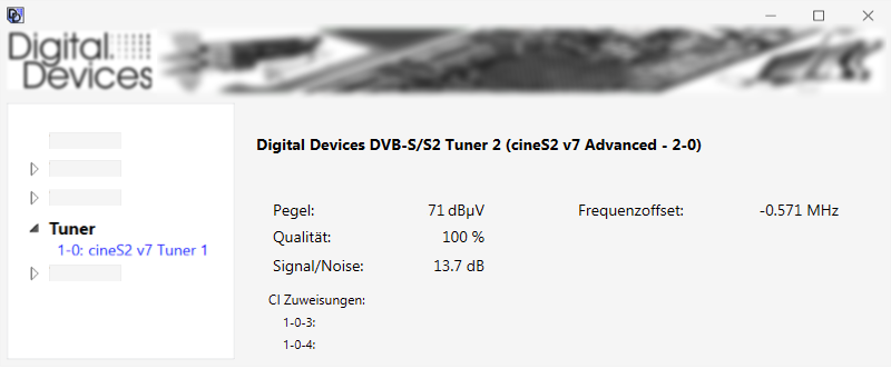
CI assignments
If a CI is assigned to the selected card or extension module, this assignment will be displayed here.
Software and applications
The Digital Devices TV software is included in your TV card package and is compatible with various applications.
Digital Devices TV
We offer the tv software Digital Devices TV for download: Digital Devices – DD-TV Download
In addition to the internal DVB-S, DVB-C and DVB-C cards you can also integrate networks such as the Octopus NET.
The application manual is available from: DDTV-Handbuch
Third party TV software providers
The TV card supports many TV applications like Microsoft WindowsÆ MediaCenter 7/8, DVBViewer, Media Portal, Gen2VDR, MythTV Instructions for various applications are available on our website www.digital-devices.de.
Technical drawing
Technical drawing DuoFlex S2
Extensions
Digital Devices TV cards and modules can be expanded and combined easily thanks to the modular design of Digital Devices solutions.
Each DuoFlex module can be connected to any TV card or bridge via an expansion connector. Even cards without expansion connectors can be integrated since the PCIe system bus is able to establish a connection. In either case additional modules are seamlessly integrated into the Digital Devices Control Center.
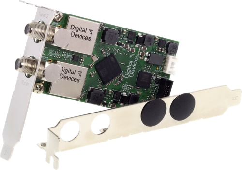
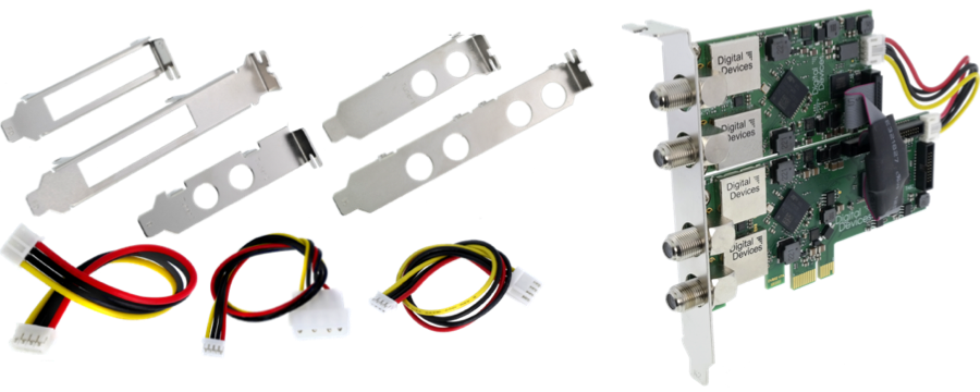
Slot brackets, assembly
Accessories for various combinations are available and can be obtained from Digital Devices.
The following figure illustrates examples of slot brackets and power connections.
Sample configuration shown: Digital Devices Cine S2 v7 with a DuoFlex S2 v4 expansion module on a combined slot bracket K (available as accessory)
Notes on data connection
If multiple modules are utilized, connected tuner modules are identified in the system as follows, depending on the TAB used:
- TAB 1 to Octopus series -> Tuner 1 & 2
- TAB 2 to Cine or Octopus series -> Tuner 3 & 4
- TAB 3 to Cine or Octopus series -> Tuner 5 & 6
- TAB 4 to Cine or Octopus series -> Tuner 7 & 8
Make sure that tuner extension modules are connected to smaller TABs of the Cine or Octopus series in terms oft numeration than the DuoFlex CI.
Note on Common Interfaces (CI)
You can expand your TV card with a Digital Devices CI-module and equip it with a CAM in order to watch encrypted programs of your provider.
Note: Please note that one will need to purchase a CAM applicable to the encryption of the provider.
Tested CAMs:
- Mascom Alphacrypt Classic/Light with Sky S02 (Firmware > 1.16/3.16) and SRG-Mascom
- Easy TV with Sky S02 and ORF
- SMIT Irdeto/Cryptoworks with ORF (2 tuners)
- SMIT Viaccess with SRG (2 tuners)
- Technicrypt CW with ORF (2 tuners)
- SCM Cryptoworks (1 tuner) ? and more
For Mascom CAMs, the protection of minors feature should be switched off when viewing Sky.
When using multiple extensions, be sure to connect CI modules to higher-numbered tabs.
Troubleshooting
Please consider the following advice, once a problem regarding your card occurs.
Please access our knowledge base for more information and assistance at: http://support.digital-devices.de/
Basic prerequisites / testing for errors
*Turn off the PC and disconnect the power cord before carrying out any checks.
Now perform the following checks:
- Are all cables and connectors properly connected?
- Is the card firmly plugged into the PCIe slot?
If the card is not recognized by the system, please try another PCI Express slot. Since some motherboards don't recognize cards plugged into a PCIe X16 slot properly. Utilizing the X4 or X1 slot should be considered.*
- Make sure using original equipment only. Do not interchange cables from different devices, even though they appear identical. They may differ in pin configuration.
- Does the antenna provide adequate antenna power?
- Make sure to implement a minimum distance of one meter to high-frequency and magnetic interference sources (TV set, mobile phone, speaker boxes, etc.).
- Turn the PC back on and carry out the following checks:
- Does the card show up in the device manager or in case of a Windows PC in the Digital Devices control Center?
- Inside BIOS, "PCI Express overclocking" should be set to 100 and not into "auto" mode.
- Does the DD Control Center or your application display a signal?
- Does the problem occur in one application only? Try it out in Digital Devices TV as well.
- Is the installed driver up-to-date? Does the problem still occur when a different one is used?
- Did you install the required codecs for playback on your system? Disable DXVA if block graphics occur with HD stations.
SAT-specific tests:
- Does your LNB need to be powered?
Note: No additional power supply is required if the connected LNB is powered by a multiswitch or if the LNB does not consume more than 5 watts (see manual of the LNB). In case of the Cine S2, an additional power supply via Sherlock connector is possible to supply LNBs with up to 20 watts
- Are the DiSEqC settings correctly configured for the specific card?
- Is either a digital or a universal-LNB / LNC present?
- If Unicable is used, check the frequency allocation within DD Control Center
Imprint & Contact
Product support and advice
Phone: +49 (0)2065 - 6989930 (Mon-Thu 09:00 - 18:00, Fri 09:00-17:00)
E-Mail: support@digital-devices.de
Inquiries from OEM and industrial customers
Digital Devices GmbH
Mittelstrasse 5/5a
D-12529 Berlin Schönefeld
Phone: +49 (0)7503 – 9300-0
E-Mail: sales@digitaldevices.de
Company registration number: HRB 14007 CB in Cottbus
VAT Id No.: DE 266 587 135
Inquiries from distributors, retailers and end users
Digital Devices Distribution GmbH
An der Geis 67
D-47228 Duisburg
Phone: +49 (0)2065 – 6989930
E-Mail: shop@digital-devices.de
Company registration number: HRB 21725 in Duisburg
VAT Id No.: DE 269 963 931
Digital Devices Produktportfolio
Digital Devices is one of the leading system suppliers for a wide range of network products with focus on broadcast technology.
The Portfolio reaches from modular DVB components over network solutions up to individual developments.
All products are manufactured and designed according to European ISO / DIN guidelines and environmental standards.
For more information oder suggestions please contact under the mentioned contact details.
Explore the world of Digital Devices at www.digitaldevices.de.